How we get the most from our FDM 3D printers
Fused Filament Fabrication (commonly referred to as Fused Deposition Modelling or FDM) is the most common form of 3D printing. Desktop FDM 3D printers have cemented their place in the design process and are utilised in-house by almost all design consultancies. In this article IDC share how they utilise the fully capabilities of their desktop FDM 3D printers throughout the design process.

Integrated functionality
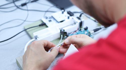
3D printing provides many opportunities for combining functionality and integrating parts. The ability to easily encapsulate springs, magnets or nuts into 3D printed parts significantly reduces assembly time and allows for prototypes to be printed and tested rapidly.
Springs
IDC recently designed a push to release mechanism for the control box of a wearable product. This mechanism was to be prototyped to inform button actuation force, button size and the quality of user interaction. The dependency on OEM spring lead times would have delayed the production and testing of this concept. To get around this, the springs were integrated into the buttons and 3D printed. This significantly reduced complexity and lead time and allowed for a fully working prototype to be 3D printed, assembled and tested in less than half a day. A range of buttons were 3D printed with different spring thicknesses and geometries. The buttons could easily be assembled and quickly swapped to vary and judge the spring force and the quality of user interaction. The actuation force of the best suited 3D printed spring was measured with a force gauge and an appropriate OEM compression spring was specified for production.

Magnets
Slicing software converts 3D CAD into g-code recognised by 3D printers. Most pieces of slicing software contain a “pause at layer” function. This pauses the 3D printer at a specified height allowing you to embed nuts, magnets or other parts before resuming the printer and encapsulating the embedded parts.

Correctly weighted prototypes
IDC recently developed a Personal Locator Beacon (PLB) for Marine Rescue Technologies. For pre-compliance testing a correctly weighted prototype was required, this prototype was attached to a lifejacket and put in a tumbler to assess lifejacket abrasion and wear during an accelerated life test. Varying simple print parameters like infill pattern and density allowed the weight of the prototype to be tuned before printing. This meant no assembly was required and the 3D printed prototype could be sent straight for testing.

Jigs and fixtures
3D printed jigs and fixtures are used extensively at IDC throughout the design process, from bracketry to interface prototypes with measuring equipment to production assembly jigs. IDC recently developed a camera bar for NCAM Technologies. Laser marking the ‘NCAM’ logo on the top of the camera bar proved difficult and time consuming as there were no flat surfaces that could be used to constrain the camera bar. Due to the curved faces and corner radii, it was also laborious to datum the laser head to accurately find the correct position in which to mark the logo.
A jig was designed and 3D printed to hold the camara bar in the laser marker. The square corners of the jig were used as a datum allowing for quicker laser set-up. This simple jig reduced production cost and time while making the marking process more robust and accurate.

Prototyping and testing at IDC frequently involves sensors and measuring equipment. Linear motion has formed the foundation of many recent projects, presenting challenges with motor positioning and linear sensing. It is often not attractive to use off the shelf, plug and play sensors due to the significant cost, bulky size and clunky interface. Especially when they need to interface with intricate and compact motion systems. The raw components, hall effect or optical sensors, however, can be extremely compact and cheap. These sensors combined with 3D printed bracketry and fixtures can result in low-profile, integrated sensors bespoke to the specific motion system.
One of IDC’s recent projects involved multi-axis linear motion. Optical sensors were integrated in low profile 3D printed bracketry. The flags, used to trigger the optical sensors, were also combined with 3D printed bracketry. The position of the flags was adjustable to allow for position and end-stop tuning.
3D printing bespoke sensor housings resulted in a significant prototype cost reduction. 3D printing allowed for the full adjustability of the sensors which resulted in quicker prototype set-up.

Optimising print time and quality
Most desktop 3D printers come with slicing software allowing parts to be printed with just a few clicks. This automates the process of part orientation, generating supports, slicing and exporting g-code for the printer. Although useful for small and simple parts, this one-size-fits-all approach to print preparation often has several downfalls on larger and more complex parts. Modifying some of the simple settings within the slicing software will allow you to control and significantly optimise surface quality, print time and material usage.
Typically, on FDM printers, a part will be built directly on the build plate with its largest, flattest surface downfacing. With more organic forms there is often no logical part orientation and the slicing software will create a large cradle of support material to facilitate printing the part.
The below example is a surgical handpiece from a recent medical project at IDC. By default, a large cradle of support material is generated to hold the part as you can see from the left print preview. As a result, nearly half of the A-surfaces are in contact with support material. Once the support material is removed these surfaces will feel rough and there will be a loss in definition of any detailed features. This approach results in a print time of 2 hours and 44 minutes and 24.75 grams of material usage.

In the right hand print preview the part has been split about its midplane and placed flat on the build plate. Two small holes have been added to the underside of each half and two small dowels have been added to the build. Once printed, the two halves can be bonded together with a few drops of super glue with the dowels used for alignment. Splitting the part resulted in a 40-minute reduction in print time and more than a 10% reduction in material usage. All A-surfaces were kept free of support which left them smoother and with crisper details. Splitting the part also gave each half a large flat surface to adhere to the build plate, this reduced the chance of warping and print failure.
It is not always practical to split and bond parts but often a simple split can reduce print time, reduce material usage and offer a higher quality part that is less prone to failure.
The above examples illustrate how IDC utilise the full capabilities of their desktop FDM 3D printers. This streamlines the development process and results in the quicker production of high quality and functional parts.
About the author
Luke Williams is a Senior Design Engineer at IDC. Luke has a deep understanding of additive manufacturing and has recently been involved in extensive 3D printing on medical and industrial projects. Luke plays a key role in a diverse range of projects, utilising IDC’s full range of 3D printing technologies to produce prototypes and functional parts. Luke’s involvement in 3D printing ranges from intricate medical components suitable for gamma irradiation to complex load bearing mechanisms.

Sign up for our top resources and articles on product development.